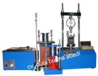
CHARPY IMPACT TESTING MACHINE[1 Mar. 2011, 22:07:33]
CHARPY IMPACT TESTING MACHINE
Capacity = 300 Joule
Length from the axis to the center of presusion = 0, 7500 m
Lifting angle of Hammer = 150, 0°
Weight of Pendulum Hammer = 214, 668 N
Momen = 161, 00 Joule
Impact Energy = -298, 275 Joule
Center of percussion = 0, 7460 m
Speed of hammer at impact = 5, 2 m/ sec
CHARPY IMPACT TESTING MACHINE
1. Purpose
The purpose of the charpy impact testing machine lies in measurement on brittleness of metallic materials. The Following is the impact testing procedure. That is, a test piece prepared is supported at both ends and impact force, given to its central part. Then, absorption energy required for breaking the specimen is measured and calculation, made on the charpy impact value.
2. Capacity and Dimensions
Capacity : 300 Joule
Model : Charpy
Weight of Pendulum Hammer ( W) : 214, 668 N
Length from the axis to the center of percussion ( L) : 0, 7500 m
Lifting angle of hammer : 150, 0°
Dimension ( LxWxH) : 1040 x 800 x 400 mm
3. Construction
The Unit consist of high precision bearings, a hammer, a dial and a hammer, a dial aand a hammer lifting device at the upper part of a robust frame, a support stand for test specimen at a lower part and hammer stopper at lowermost part.
4. Pendulum System
A pendulum shaft provided with a hammer is put in the bearing and metal futtings for pointer guide, fixed to its end. The Lifting angle and swinging-up angle of the hammer are indicated by the pinter. As For the positional energy for impact bending of test specimen, it is not a mere weight of the hammer. It also includes the weight of ball bearings at rotary part of hammer and at both ends of the said shaft. The total value of the metal fittings for pinter guides is the weight for calculation of positional energy. Usually, it is called PENDULUM SYSTEM including them.
5. Hammer Lifter
The Hammer lifter consist of hammer hook, worm gears and bevel gear handle. This unit has such a constructuin as mentioned hereunder. That is, when the hammer is lifted up or down or under vibration, if it is caught by hook, the hook lever is designed to be as long as possible in order to prevent impact vibration from being given to the measuring device for energy. As the same time, the vibration given to the worm gears is eliminated by buffer spring installed at the worm shaft.
6. Measuring device for Energy
The angle dial is graduated eith degrees ranging from 0 to 180° with one degree as unit 1 line, the numerals showing angle are privided every 10 degrees, i. e. 0° , 10° , 20° etc.
The Said numerals are stamped red and black in bith lifting up and swinging-up directions. The said dial is fitted to the worm gear with the pendulum shaft as center. The Pointer showing angle is installed at the shaft center od the dial in such a way that it holds of the plate spring lightly. The lifting angle and swinging-up angle are indicated with the metal fitting for guide for pendulum system.
7. Support Stand for Test Specimen
The impact part of support stand for test specimens for this unit has been subjected to an annealing treatment. And the frame has been subjected to a groom treatment for attaining Plug-in tightening, its end provided with the metal fittings for reception of impact. In Conventional types of support stands, if test specimen is broken pieces should strike againts the support stand, resulting is reversal, the hammer will be broken very often. Improvement has been made on this unit and broken pieces fly away toward the outside.
8. Hammer Stop Device
Hammer stop Device udes disk brake system. When the hammer impacted of the specimen, the pendulum will be moved, for the stop pendulum, push the handle with foot.
9. Caution For Installation
1. Complete foundation work must be be done for foundation concrete as instructed according to insatallation drawings for giving impact vibration.
2. Horizontal must be checked by placing a water level on the receiver stand for test specimen.
3. Place an attached 10 mm standard gauge on the receiver stand for test specimens and adjust it to the position where the hammer blade contacts lightly.
4. When the test specimen is broken, broken pieces fly away in the forward direction. Accordingly, install it in such a way the broken pieces fly away in the wall direction.
10. Testing procedure
1. Inspection Before Test
a) Apply the position for hammer to the receiver stand for test specimens and check whether or not the hammer is located at normal position. If the blade surface of hammer is not in accord with the gauge groove, loosen the tightening bolts at rotary part of hammer and adjust it to the correct position.
b) Adjust the inteval of the receiver of the receiver stand for test specimens by means of a position gauge for test specimens. The standard specified is 40 ± 0, 2 mm. The gauge has been designed and manufactured in such a range.
c) Place the 10 mm standard gauge on the receiver stand for test specimens and apply the blade edge of hammer to the gauge. When the pointer is applied to the metal fittings for guide, if the pointer indicateds 0 and 180° vertically, it will be correct. If different, loosen the nuts for metal fittings for gauge and adjust it to the specified position.
d) Prepare the best specimen and let the notch groove surface the inside of the receiver stand for the test specimen. Insert the position gauge for test specimen between the receiver stands at both sides and places the test specimen un such a way thet gauge pin is in accord with the notch groove for test specimen.
2. Impact Energy
a) Hook the hammer with the hook for hammer lifter
b) Lift the hammer to the max lifting abgle ( Stopper Position) with the handle. In this case, the pointer must indicate the lifting angle with the guide metal fittigs.
c) Hold the hook release handle. Drop The hammer the specimen position. After breaking of the test specimen, the swinging-up angle is indicated. The said angle is the satndard for calculation of absorption energy.
d) AS for energy required for breaking, calculate according to TABLE FOR ENERGY.
e) As for the energy E required for breaking specified in standard document ( BS, JIS, ASTM, etc ) it can be calculated from the following formula :
E = M ( 1- cos ± )
Where,
E = Energy
M = Momen
= W x L ( Nm)
â = Lifting angle of hammer
With energy as one place, count as one fractions of more than 0, 5 inclusive and cut away the rest.
f) Calculation Of Energy In Attached Table
When the hammer drops from the lifting angle ( ± ) , if it goes up to the swinging-up ( D) after breaking of the specimen will be E1-E2. But, in this case, such energy loss and friction or rotary parts, bearing, pointer and air resistance are not include.
E1 = Positional energy owned by hammer at lifting-up angle ( ± )
E2 = Positional energy owned by hammer at swinging-up angle ( ² )
E1 = M ( cos â ² 1 â cos ( ± â ² 1 )
E2 = M ( cos â ² 2 â cos ( ± â ² 2 )
The aforementioned formula is specified. In this formula, WR and a are in herent values of the testing machine. Accordingly, it si possible to know the energy ( E Joule) required for breaking of the specimens from the swinging up angle ( ² ) of hammer. Calibrate the respective testing machine and the value of the energy for one degree up to 150° C of the swinging-up angle are found out and shown in the list. In actual test, the hammer uis made to drop from the specified lifting-up angle ( ² ) is known from the pointer. From the said angle, the energy required for breaking of the test specimen can be known from the list for energy.

 Ke Menu Anggota
© 2024 Indotrade.co.id. Hak Cipta Dilindungi Undang-undang.
Ke Menu Anggota
© 2024 Indotrade.co.id. Hak Cipta Dilindungi Undang-undang.